My Bell 47G2 Panel for Fly-inside

So after messing around with the 47 and with there being little chance of a usable 206 for a couple of years I’ve decided to put some effort into making a panel for the 47 and possibly flight controls.
I have some Bell documents including the illustrated parts manual (which is where I get a lot of the basic shapes from) to get me started.
I wasn’t allowed to ship my model paint collection when I moved to Switzerland last year so now with lockdowns easing I hopefully will be able to start building a new collection!

The first item I’ve tackled is rather small and it’s a four way magneto switch. It uses a standard rotary switch with 3D printed enclosure and lever. I’ll print a decal for the face after I paint it.
A very small part of the puzzle, but a good start!


I will be focusing on the instruments, grimes instrument “browlights” and the mixture/carb heat quadrant first and then design the panel itself. It looks to be pressed metal giving it curved edges. That actually makes a bit tricky so I’ll need to think more about that one.

Next up the quadrant and the Carb air/Filter Air Temp gauge.
Here is a quick screenshot of the quadrant render. It’s off to the printer now!

Cheers,
Stuart

2 Likes

That’s quite an interesting project, Stuart. Please keep us updated!

Great to see, keep us posted. are you using an outside 3d printing company? If so is it in the UK.
Regards
Dave

Cheers Dave.
I print all the pieces myself. I have a Prusa i3MK3S+ and an older Prusa i3MK2S and they work great! They are expensive, but they just work without any messing around or tweaking. From a prototyping point of view I find it a lot better to only have to troubleshoot my designs and let the printer worry about itself.
What I should have said was I sending the files to my printer in the other room! Sorry for the confusion!

:slight_smile:

Hi Sergio,

Will do! There is a lot more to come. Just attempting to extract it from my brain :crazy_face:
There will be a delay on some of the gauges as I’m awaiting parts from China. It will give me some time to work on the gauge faces and the brow lights. I intend them to be fully functional so I’ll need to adapt the original design to maximize the LED brightness I can get out them to angle onto the gauge face without too much glare.

Cheers,
Stuart

And here is the prototyped quadrant. I’m generally happy with the result.
A few tweaks to make and obviously paint. I reduced the size of the carb head square knob as the original design was comically large once printed! I’m using aluminium bar 12x3mm for the levers. This is readily available in most hardware stores.

Cheers :grinning:

That looks fantastic!!! How are you connecting pots to those levers? Are they concentric or offset?

Jon it’s a work in progress. So I haven’t gotten that far. I’m planning putting the pots inside the panel with lever arms connected to the quadrant. I might use bicycle brake cables with a rigid bar fitted over part of it close to the quadrant attach point. (Not unlike the actual 47 set up with cables).
I’m busy with the gauges faces at the moment, so one I get back to the panel enclosure I’ll progress this.
I’ve designed a Manifold pressure (Older style 10-75inHg I just prefer the look in this old aircraft), RPM gauge and the carb temp/filter air temp faces so far. I have the cad models for some of the additional pieces I need to get these finished. These are mostly modified from my Bell 206 gauges. I’m working on the triple needle gauge for the Oil temp, Oil pressure and the Fuel Press at the moment and the Cylinder Head temp is next, followed by the ASI, VSI, Fuel Qty and the Load meter.

Cheers,
Stuart

Just a quick update to say I’m still working on this project. I haven’t printed anything else yet. I am also redesigning the quadrant as I’ve some better reference images to go off.
I designed the panel, grimes eyebrow lights (for 3 1/8, 2 1/4 and 1 1/4 gauges), switch guard and switch quick shut off as well as a few other smaller bits.
I have all the gauge faces complete’ish. The Cylinder head temp gauge needs a do over as I drew the index points from a point to high on the gauge. The rest all went really well with no major hiccups along the way.
I should be in a position to start building parts of this in a few weeks.
See the render below. (I haven’t made any decals for the switches or breakers as of yet).


I’ve included a grey panel so you can see more of the detail.

Cheers
Stuart

Hi,
I’m continuing to modify the design so not too much progress to report.

I’ve made some new stepper motor instrument designs with anti backlash built in improving the accuracy. I started with the altimeter which the face can be seen in the lower image. It will be a dual scale instrument, as MS refuses to give Hectopascals in the ATIS! The good thing about starting with the altimeter is it’s so complex the others shouldn’t take long to bash out.

I’m finally sending the flat main instrument panel design out to be cut on a waterjet. Hopefully I’ll have it back around Christmas time. I have shortened the panel from my original design down to a max height of 600mm when flat. I don’t have accurate dimensions, but everything I want to use in it seems to fit.

I’ve done some tweaking of the Grimes small eyebrow lights and fixed the inverted word "Pressure: on the manifold drain control.

I have spent quite a lot of time on the throttle quadrant and its now a complete redesign as I found some good reference photos, a few drawings and saw a youtube clip of a generic quadrant being modified by a great engineer, Ian Slater on the Typhoon Legacy channel. If you really like watching brilliant machining skills and want to follow a rebuild to airworthy status of a WWII Hawker Typhoon (JP843) I’d strongly advise you watch this channel. The lever knobs are currently unchanged. I will be reducing the size of the legends on these. The quadrant functions exactly as the real one. It’s still mostly 3D printed with some Aluminium bar stock added for the levers.

A couple of renders for your amusement :slight_smile:


Cheers,
Stuart

Okay I know it’s taking forever! Sorry. Progress is being made.
The panel is progressing with a few gauge mods and radio and transponder designs.

Gauges
The gauges had to undergo a mechanical redesign as I wasn’t happy with the motion of the needles, but I’ve arrived with something I’m happy with.

I’d love to take credit for the panel, but when I approached a local metal shop to cut my design the quote was higher than the cost for a real one that showed up on ebay. It was reconditioned by Westland helicopters in the seventies and remained bagged since then. I can see some of the original switch legends under the paint so it obviously needed a respray. The legends were then reapplied by hand with a paint pen. I’ll be removing this and applying decals instead.
My design for the panel was pretty close to the real dimensions. I hope to readjust it to the real dimensions and make that available.
The eyebrow lights were reasonably priced, so I picked them up on eBay too. I had already designed these in CAD but the prospect of printing, filling, sanding and painting was less enthusing than the purchase cost!

Flight Controls
I have a genuine bell 47 cyclic, collective and pedals, so I am designing a new simbase using 40series aluminium extrusion to hold it all. My existing base is mostly timber with a small steel frame under the seat that holds all the linkages and electronics. It isn’t capable of housing the 47 controls as well as the 206/407 bits. so the new design was called for. This will allow me to swap in my 206/407 controls as needed with only minor tinkering required between swaps. All the linkages, torque tubes and will remain attached to the base with a swap of the floor, pedals, cyclic and collective. I know it sounds like a lot of work, but I’ve been playing with the CAD and I think it’s doable.
The throttle will be controlled like the original bell with a seperate shaft that will use a correlator effect with a DIY cambox modelled off some reference photos so it will be influenced by the collective position with more throttle being applied as collective is raised.

The cyclic was covered in rust and it took quite a while to clean it up. All the bearings were good once cleaned. All the aluminium castings and the rest of the cyclic were cleaned, stripped and repainted. The friction was seized with rust but eventually freed up. Likewise the friction bearing (open type) all its bearings were seized and covered in rust. After a long soak in penetrating oil it came up great and functions as it should. I packed it with grease before reinstallation.
I plan to have the gauges finished by the end of August and the base over the next month or two.
It’s starting to feel real and I’m looking forward to sharing the results!

Cheers,
Stuart :slight_smile:

You don’t owe anyone an apology. It’s your project, finish or don’t finish it. All on your own time and at your own discretion.
I am curious about the center stack. I asked RotorRick (Flyinside Dev) for the dimensions of it but He doesn’t have it available to share. I was wondering if you could accurately measure the location of the switches from the top and left side for me. I’m building a center stack for the G47 as well. I fly in VR so it has to be accurate so I can just reach out and physically flip a switch or turn a dial.
I noticed you don’t have a collective. I designed and built a collective with swappable heads. It’s on Thingiverse with build vids on YouTube.
Helicopter Collective with inter-changeable heads by Thick8 - Thingiverse

Collective Huey head (youtube.com)

Happy to help. Please let me know if you want measurements in inches or mm. :grinning:

A few more photos of developments…

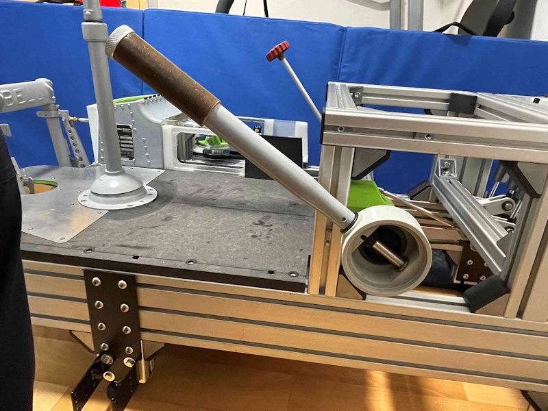
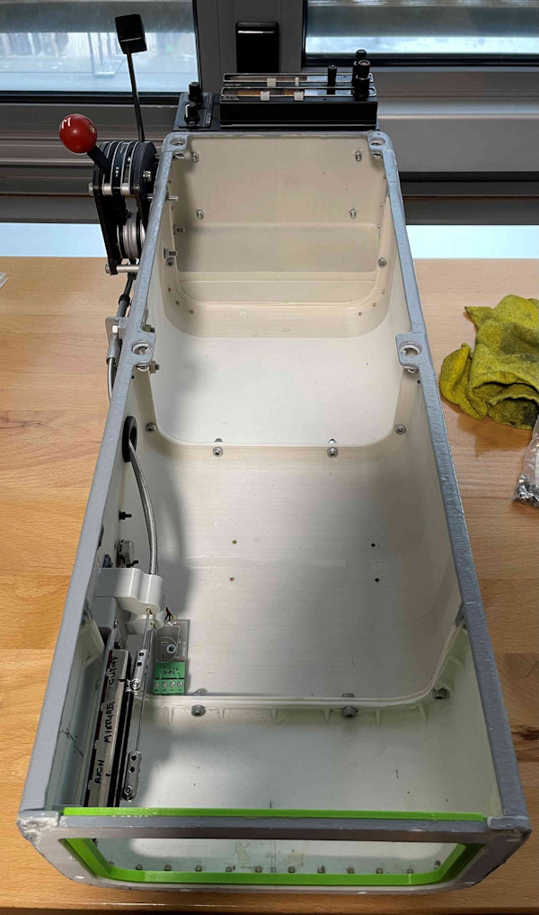
The 40 series frame, 16mm MDF floor. Additional frame to support the pedestal and centre tunnel.

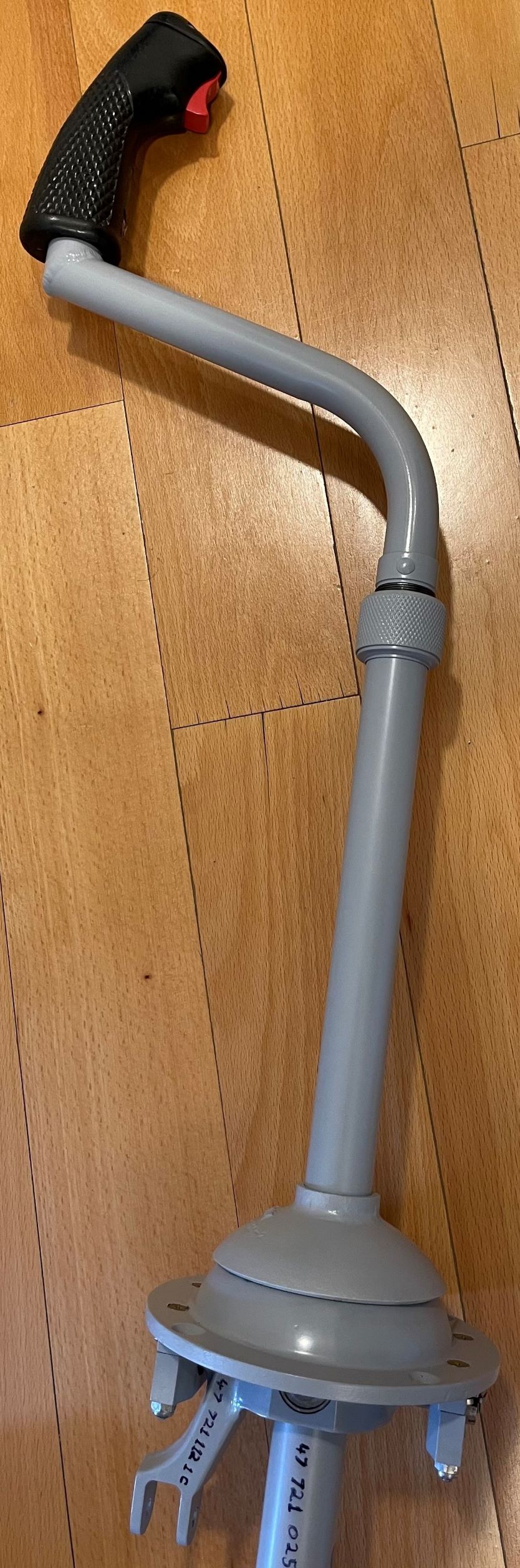
Side On with friction shaft and pedestal base visible in the background.

Close up of throttle gears inside collective bell housing.
CollThr

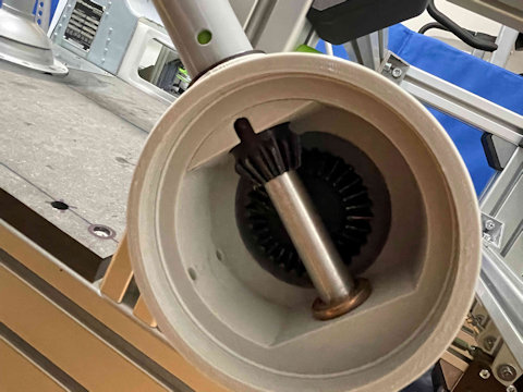
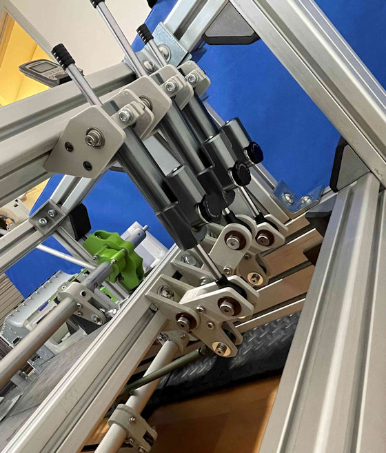
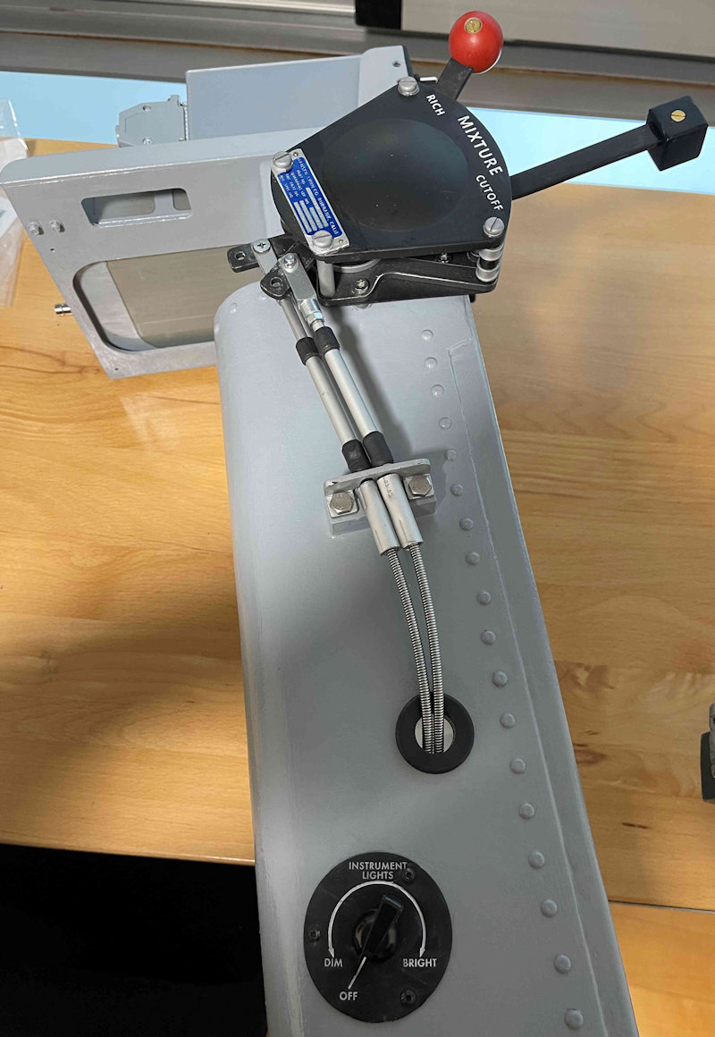
As mentioned in previous post, I’m using motorcycle steering dampers to provide some resistance on the collective and cyclic controls. I have replicated the same linkage setup found in the real aircraft to also to give a more realistic feel. I intend to add a wire rope loop connecting to a rotating drum to add an additional bit of resistance and hopefully a more authentic feel to the pedals. You can just see the cutout on the collective shaft for the throttle linkage. There is an inner shaft connecting to the large gear in the bell housing. This will be connected via an additional shaft and then to my interpretation of a Bell 47 cambox and then to an additional hall sensor.


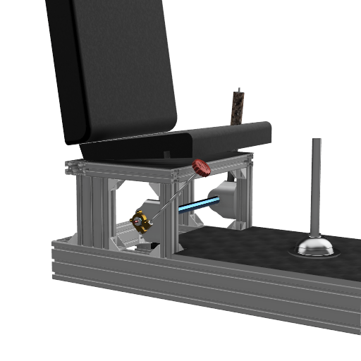
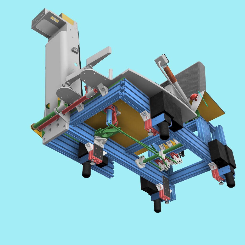
You can see all the linkages in this render from the cad model. I didn’t feel like lifting the sim up on its wheels to take a photo! It’s designed that with the pedestal and cyclic removed along with the seat folded, it can be transported and moved through normal doorways.


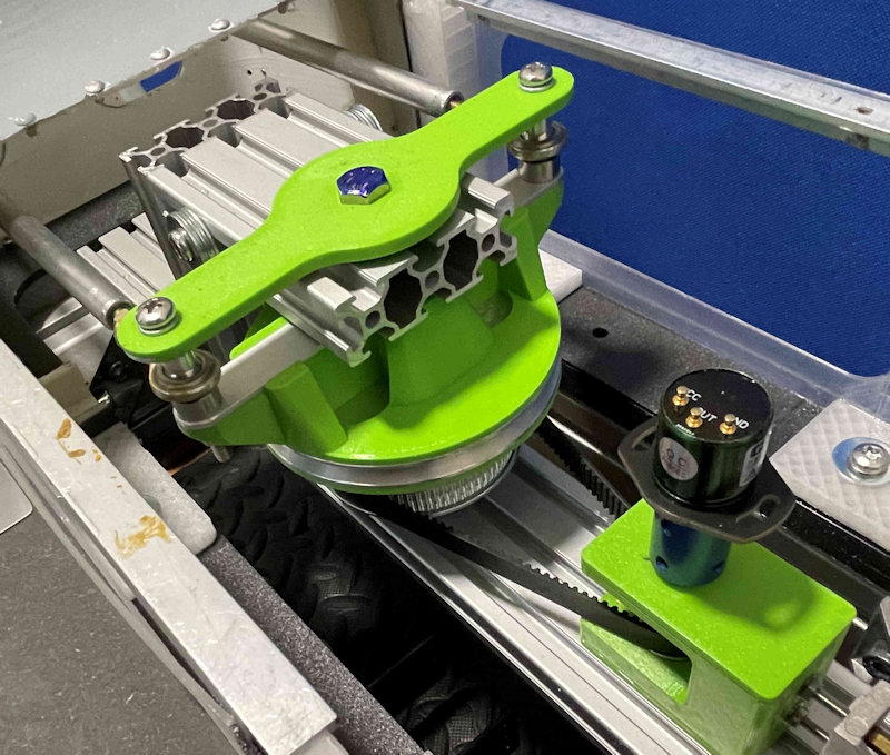
This is the same gearing I used on my 206 build with HTD3M belts and pulleys connecting to a hall effect rotary sensor. There will be a mount that will secure the Hall sensor above the small pulley carriage. The carriage slides on the 20 series rail and is tensioned using two M3 bolts.

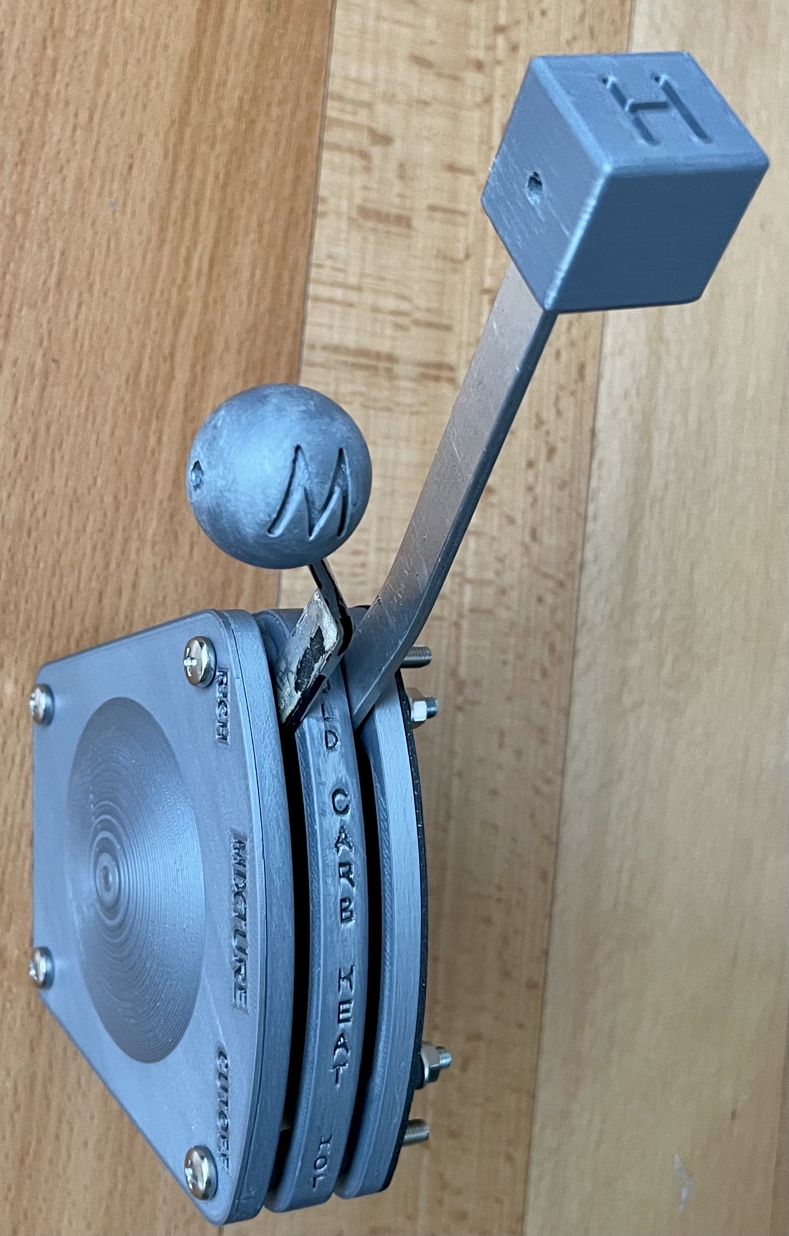
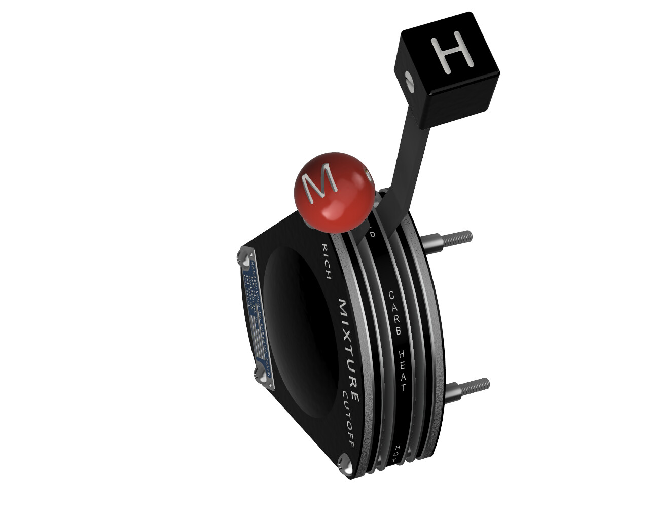
You should be able to make out the routing of the push pull cables from the mixture/carb heat quadrant. They are routed through the side of the pedestal and then are connected to a sliding potentiometer board.


The cables are visible here along with the quadrant, instrument dimmer control and radio tray. The smaller box is the audio panel.

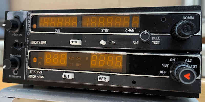
These are the radios I settled on. As yet they are not functional as I need to sit down with mobiflight and connect it all up.


Designing all these parts from scratch has taken quite some time. I am very happy with the overall look of all the component parts and I am determined to get them all together and working soon.

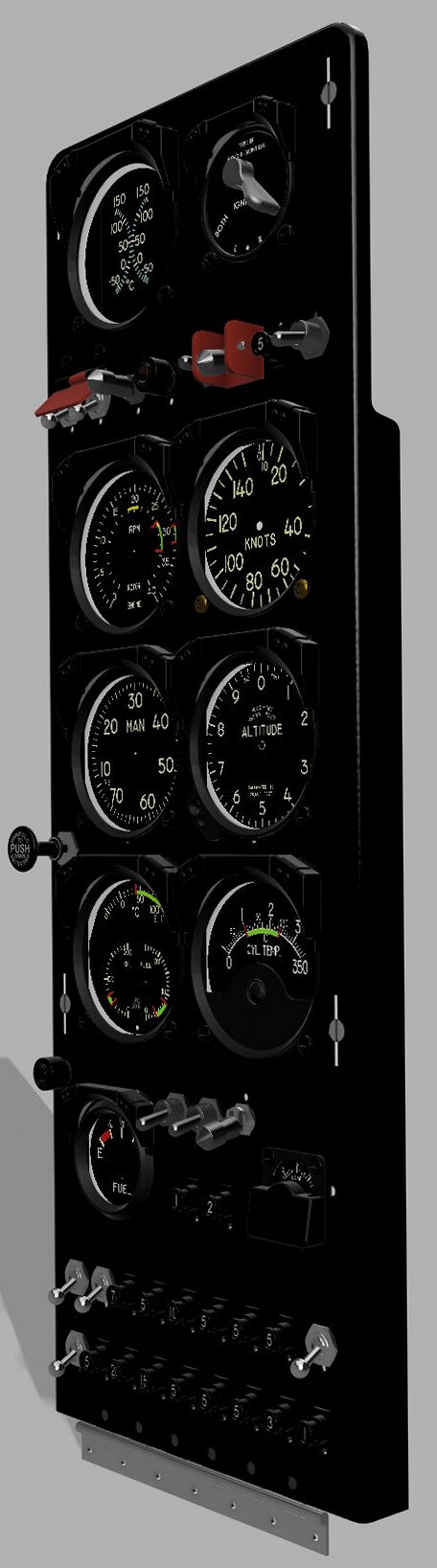
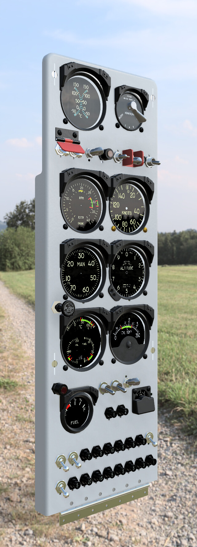
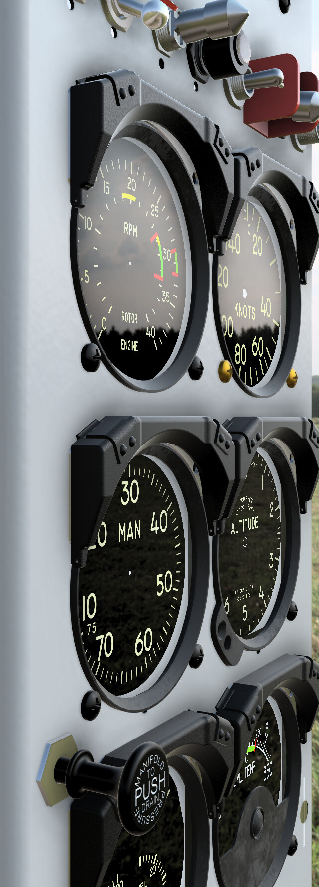
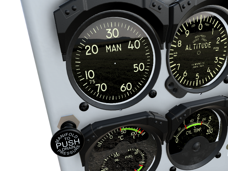
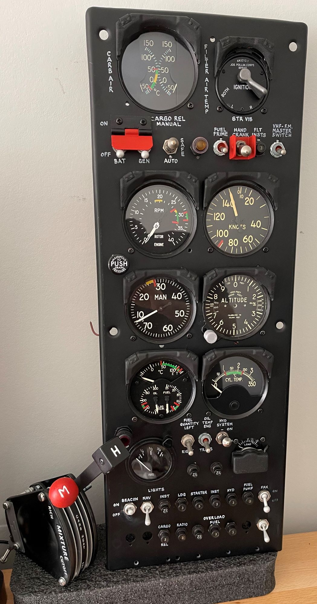
The instrument panel itself has been emptied of all gauges as I’m doing a few more revisions on the gauges and also the mounting set up for the arduinos.

I am hoping to have the flight controls fully functional in a few weeks. The panel will follow a while after that once I have some new parts.
I’ll follow up soon with some more information.

Cheers,
Stuart :grinning: